GPIO
The GPIO (General Purpose Input Output) allows you to turn on LEDs, react to button presses, or do just about anything.
Our BrainBox has 4 GPIO pins that you can control. Before you do anything with a pin, you must first set its’ mode.
There are 4 modes:
| Mode | Python | Description |
|---|---|---|
| Digital Output | robot.OUTPUT | Allows you to write a high or low signal |
| Digital Input | robot.INPUT | Allows you to read a high or low signal |
| Analog Input | robot.INPUT_ANALOG | Allows you to read a voltage, like a voltmeter |
| Pullup Input | robot.INPUT_PULLUP | Like input, but uses a weak pullup resistor |
Python
To write a digital signal on pin 0:
R.gpio[0].mode = robot.OUTPUTR.gpio[0].digital = TrueTo read a digital signal on pin 1:
R.gpio[1].mode = robot.INPUTprint(R.gpio[1].digital)To read an analog signal on pin 2:
R.gpio[2].mode = robot.INPUT_ANALOGprint(R.gpio[2].analog)To read a pullup signal on pin 3
R.gpio[3].mode = robot.INPUT_PULLUPprint(R.gpio[3].digital) # Note that this output will be inverted - True when the connnection is open, and False when closed.Here’s a more complete example:
import robotimport time
R = robot.Robot()
R.gpio[0].mode = robot.INPUTR.gpio[1].mode = robot.INPUT_ANALOGR.gpio[2].mode = robot.OUTPUTR.gpio[3].mode = robot.INPUT_PULLUP
outputState = False
while True:    # Read the values of 0 and 1    print(R.gpio[0].digital)    print(R.gpio[1].analog)
    # Switch output state and send it to 2    outputState = not outputState    R.gpio[2].digital = outputState
    # Read the value of 3    print(R.gpio[3].digital)
    # Pause for 2 seconds    time.sleep(2)
Blockly
The GPIO blocks can be found in the GPIO section, and function similarly to the python.
Pull-ups
The BrainBox possesses the ability to enable a built-in pull-up resistor on any input pin. This takes a small amount of explanation.
Normally, input pins are not connected to anything - known as “floating”. In this state, they might read high or low, or different values depending on their environment (due to anything from cosmic rays to the wiring in the building). This is obviously not good for consistent control.
Many pieces of off-the-shelf electronics that have some form of standard I/O output will connect this pin to 5V (high) and 0V (low) when required, so this is not a problem. However, for simple electronics, a microswitch for example, you would normally be required to connect a resistor between the input pin and 5V (a pull-up resistor), or between the input pin and 0V (a pull-down resistor) to keep the input in a known state until the switch overrides it by connecting directly to the opposite state.
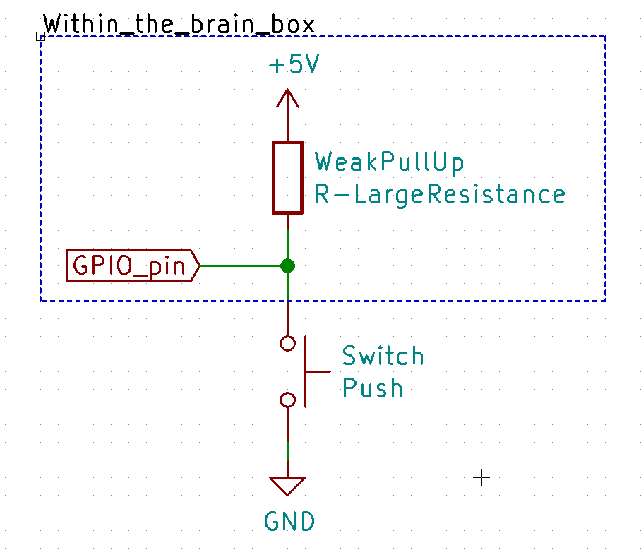
However, the built-in pull-up resistor alleviates this need. It essentially wires in a resistor connected to 5V, meaning that when this option is enabled, an input pin will “default” to being high. This means you can simply connect a switch between the input pin and a ground pin without any need of resistors - when the switch is open, the pin will read high; when closed, it will read low.